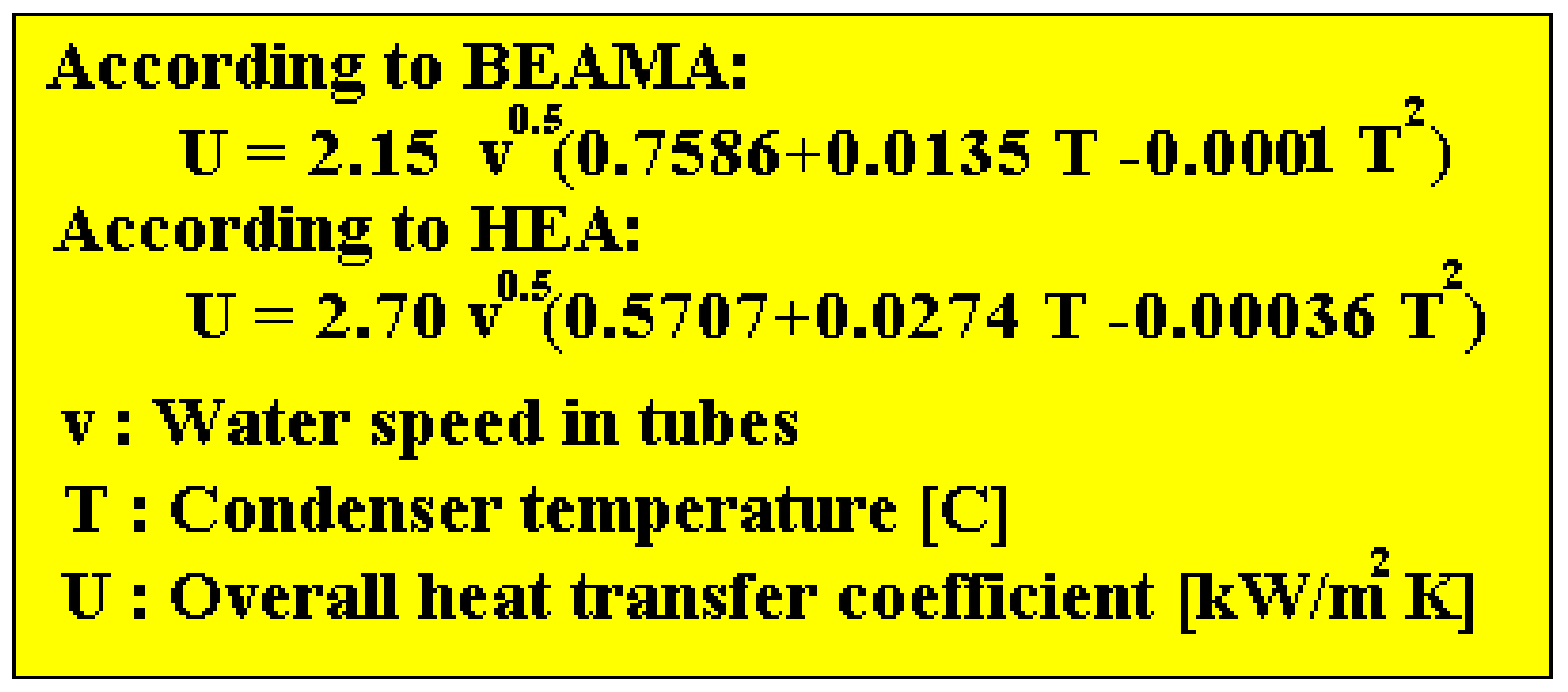
Refrigerant outlet subcooling degree C. Condenser capacities for 60 Hz are located in Table 4.

Molasses Cooler Design Molasses Preservation Properties Of Molasses Cooler Designs Concept Design Design
Condenser design calculation tool.

. Adirect contact condenser where vapors and. Lets consider a case where a 10 KL SS reactor is available and we need to select a condenser for that reactor. Select a solvent having high volatility.
Thermodynamic Design of Condensers and Evaporators. Condensers are very widely used in process industries. Determine the amount of cooling water required in jet condenser to condense one kg vapour if cooling water inlet and outlet temperature is 20 0C and 30 0C respectively.
The water flowing through the peripheral holes. Avacuum condenser sometimes placed behind a precon-denser. Thermodynamic Design of Condensers and Evaporators.
These capacities are given in MBHTD. M 2556 1256 4187 58 kg. Q p v c S 1.
Barometric Leg Calculation formula. Thus requiring an iterative calculation procedure. So Step - 1 is done.
The Multi-Jet Condenser is also used where the vacuum handled is not high and a moderately large terminal difference is permissible. Your job is done. It is the simplest design of all barometric condensers and requires no auxiliary air pump or precooler.
Acondenser with a heat transfer surface that sep-arates vapors undergoing condensa-tion from a cooling fluid. 2 The air-cooled condenser The air-cooled condenser is a steam-air heat exchanger composed by several modules such as that sketched by fig. It is a measure of efficiency of condenser operation.
Condensate leaves at 45 C calculate the quantity of cooling water required condenser inlet and outlet cooling water temperatures are 29 C and 37 C respectively. Ad Manufacturer of Barometric Condensers vacuum components and systems. Calculate the Condenser Capacity for that boil-up.
This tool is not validated for detail design. It uses a chilled cooling fluid to affect additional condensation and product recovery. A typical forced-draft air-cooled condenser is depicted in Figure 4.
Condenser Design has had 1 update within the past 6 months. Air inlet temperature C. The condenser is generally employed where low cost water is available in ample quantity.
Account the design and operating data of a condenser installed in a 400 MW combined cycle power plant still operative in the Italian electricity market. Multi-jet Multi-jet spray type Multi-spray and Counter-current designs. Swetang Patel Chemical OP 6 Aug 20 1347.
Divided by the inlet pressure p v c von 1000 Pa we obtain a pumping speed S 1 von 0397 m 3 s -1 or 1429 m 3 h -1. Air inlet flow rate. Calculate the maximum boil-up of the selected solvent.
Hello I need the calculation or formula for the barometric leg to check the u loop pressure drop for condenser to column reflux. We obtain a gas throughput for air of 12 Pa m 3 s -1 and for water vapor of 385 Pa m 3 s -1 together 397 Pa m 3 s -1. A barometric leg is basically a condensate drain that consists of a leg pipe between the pre-condenser and the hotwell.
Row tube spacingDH mm. This Multimedia Edition contains interactive features that bring the rigorous and authoritative material from HEDH to life. Convert the THR calculated in step 2 to MBHF TD by dividing by 1000 to get THR in MBH.
A down flow type surface condenser is designed to handle 110 TPH of steam the steam enters the condenser at 012 kgcm2 absolute pressure and 09 dryness fraction. Multimedia Edition of Heat Exchanger Design Handbook HEDH is the standard reference source for heat transfer and heat exchanger design. Some cold water cascades through the peripheral holes in the lip of tray the balance of the cold water falls through tray perforations.
It is probably the ideal type where load conditions are constant and there is little air leakage. Calculate Design Condenser TD. It consists of a tube bundle normally with finned tubes over which air flows in crossflow.
Valuable hydrocarbons or water are common constituents in oil and gas downstream processes. Cold injection water is conveyed by a central pipe up the length of the body to the rain tray. Take heat of vapour H as 2556 kJkg at 30 0C and specific heat of cooling water as 4187 kJkg.
In vacuum pump system design pre-condensers should be considered if a large part of the gas load is condensable. A guessed T s value is needed to calculate. An air-cooled condenser is typical of a tube-side condenser.
At the actual condenser pressure is known as the terminal difference. Initial condenser widthLD mm. When having to generate a vacuum condensers are installed to reduce the flow of vapor to suck and therefore increase the vacuum reached.
The air flow is driven by fans either in forced- or induced-draft mode. Design Condenser TD Condensing Temp Ambient Temp 110 95 20 TD. 2100 Page 4 International Refrigeration and Air Conditioning Conference at Purdue July 16-19 2012.
Download Condenser Design for Windows to perform thermal design calculations for shell and tube condensers. In food processing refineries or even air conditioning. The Sugar Engineers condenser design is the of the rain-tray type.
Condensation starting temperature C. The simplest design of all barometric condensers and requires no auxiliary air pump or pre-cooler. The first step is to calculate the gas flow from the chamber.
Face tube spacingDV mm.

Barometric Leg Technical Data Dekker Vacuum Technologies

Surface Condenser Difference Between Jet And Surface Condenser Thermal Power Plant Condensation Surface

Condenser Calculation Using Thermo Utilities V2 0 Ms Excel Add Ins
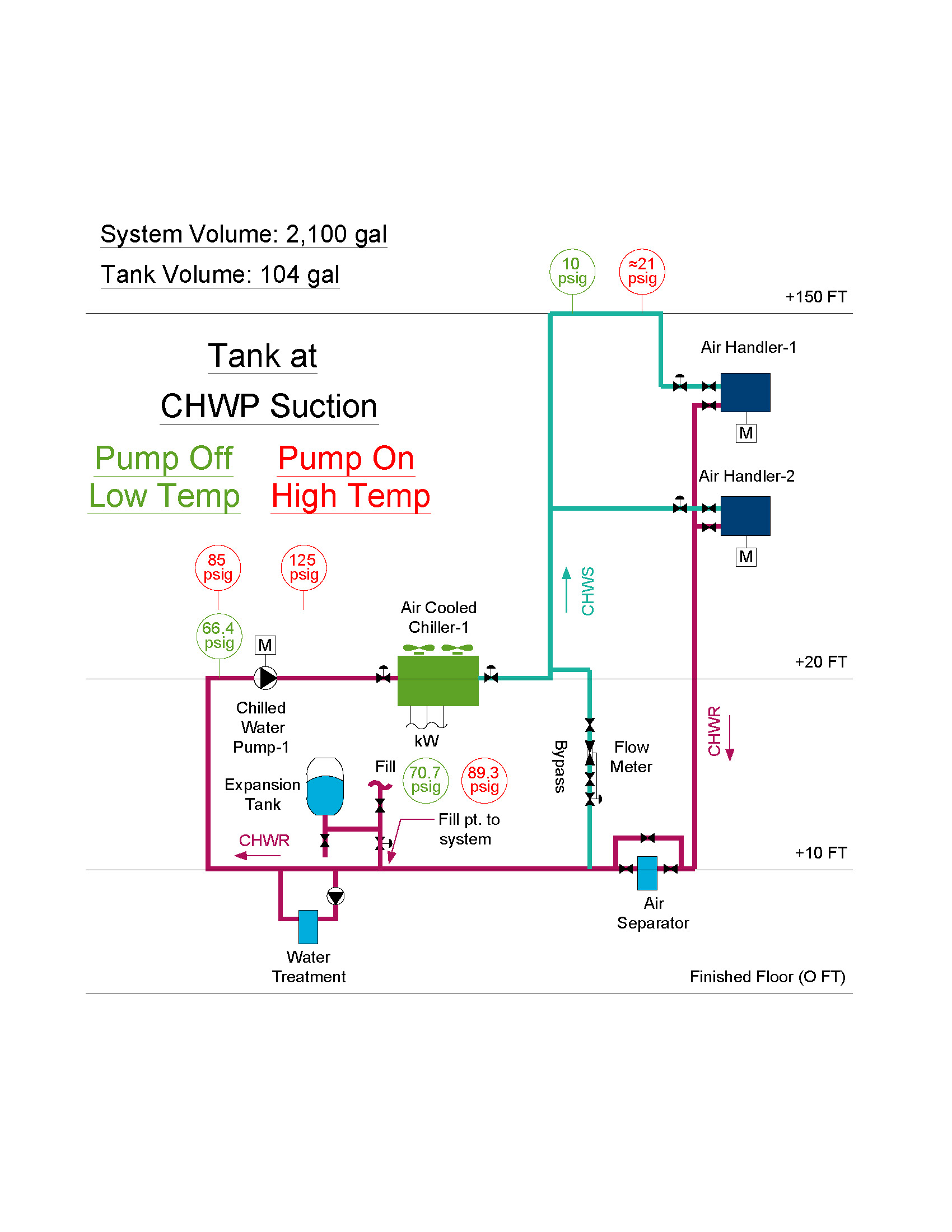
Expansion Tank Design Guide How To Size And Select An Expansion Tank For A Chilled Water System

Barometric Jet Condenser Complete Explanation Youtube
Condenser Calculation Using Thermo Utilities V2 0 Ms Excel Add Ins
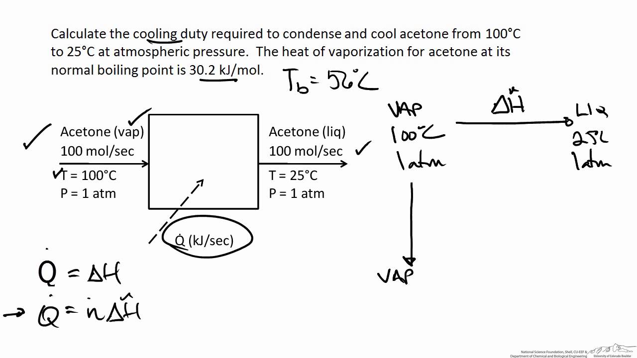
Energy Balance On A Condenser Youtube
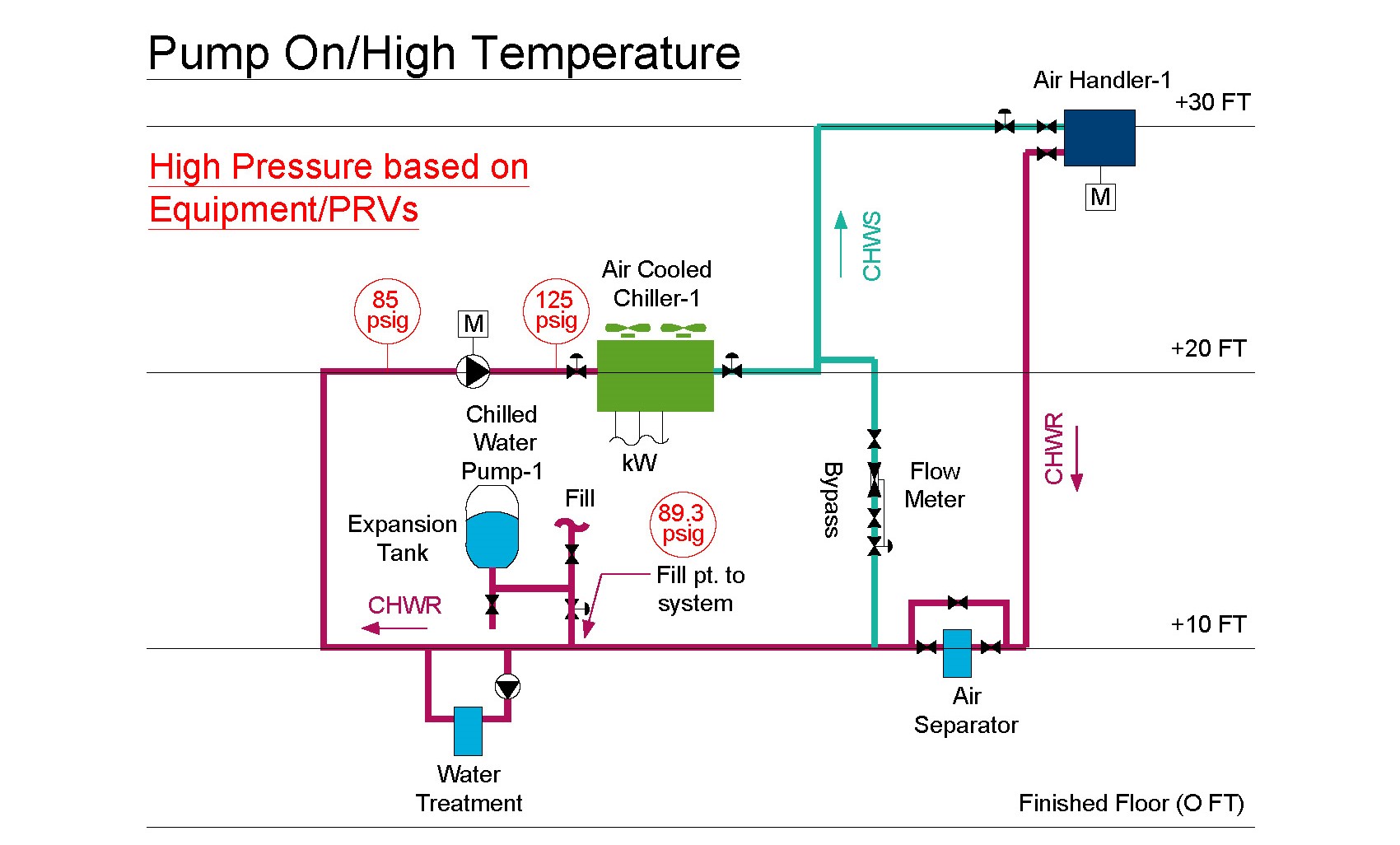
Expansion Tank Design Guide How To Size And Select An Expansion Tank For A Chilled Water System
0 comments
Post a Comment